Research Article
Volume 2 Issue 1 - 2020
Optimizing the Design of an Alkaline Water Splitting Device Test cell for Renewable Energy Storage as Hydrogen.
ESRI, College of Engineering, Swansea University, Swansea. SA1 8EN UK
*Corresponding Author: Charles W. Dunnill, ESRI, College of Engineering, Swansea University, Swansea. SA1 8EN UK.
Received: July 20, 2020; Published: July 27, 2020
Abstract
The use of alkaline electrolysis for the production and storage of hydrogen gas is an effective, scalable, and efficient method of storing renewable energy. Optimization of a specific alkaline electrolysis device is achieved by iteratively modifying and improving upon the geometry of the device. Methods to reduce electrolyte leakage from the cell are successfully developed and the performance benefits of reduced cell width investigated. Well-understood electrochemical principles were used to further characterize the performance of the various cell designs investigated. The possibility of further design improvements to the cell are discussed, such as the feasibility of incorporating zero-gap technology into the device. Scale-up to pilot scale systems is also presented demonstrating the linear scalability of the design.
Introduction
Growing concern over the environmental impact of fossil-fuel use continues to lead to the search for cleaner forms of energy. With the International Energy Association predicting global energy use to continue to rise by up to 50% in 2040 compared with today’s consumption [1] an alternative to our current fossil-fuel economy must be found to sustainably meet the needs of the future population. Globally, the primary sources of energy production are predicted to transition from carbon-intensive non-renewables to cleaner, renewable sources such as solar, wind and tidal energy. However, the increasing dependence on such intermittent energy sources poses a significant engineering challenge, as energy production cannot be controlled to match the fluctuating demand of a power grid [2,3]. A suitable method of intermediate energy storage is therefore necessary to meet demand during periods of shortfall in production, such as at night for solar energy.
One promising solution is the use of hydrogen as a universal energy vector and a shift towards a hydrogen economy [4,5]. Conventionally, the “Hydrogen Economy” meant that hydrogen would be produced at the source of renewable energy generation, then transported over large distances and stored in large amounts, for supply to cities [6]. Hydrogen has the potential to de-couple supply from demand facilitating the realisation of a 100% renewable energy landscape. Hydrogen energy is well suited for the use in distributed energy production systems, and has a number of applications for providing energy storage as well as heating fuel for domestic purposes, with a number of demonstration systems in place verifying the feasibility of domestic production and consumption of hydrogen [7-10].
The production of hydrogen via alkaline water electrolysis provides the ability to effectively store and distribute energy from low-carbon renewable sources such as solar, wind and hydro-electric systems [11-13] in a Low-Cost, high efficiency manner. Water electrolysers present several attributes that make them suitable for a shift to an intermittent and distributed energy production grid: they offer elasticity with respect to required input power, are highly scalable with systems ranging from a few kilowatts to over one hundred megawatts in large scale applications [14], and their relative simplicity of construction makes maintenance by non-specialists feasible, as well as deployment in developing countries. The use of alkaline electrolyte allows for steel electrode compared to the platinum catalysts needed in acid or PEM based electrolyser, hence providing a low-cost alternative. [15-17]
This paper mainly focuses on the design optimisation of a small-scale water splitting device aimed at a bench test cell but scalable to the domestic and small-scale production market. A number of parameters determine the overall performance of a water-splitting device and therefore a specific design’s suitability for purpose. These parameters are: energy efficiency, rate of hydrogen production, product gas purity, physical footprint, and the relation of these performance factors to cost. Electrolyte leakage also presents a concern as the design needs to account for methods of minimising this issue without including serious compromises in terms of cost or functionality.
Electrolysis Theory
Water is split into its constituent elements of hydrogen and oxygen within the water electrolyser according to the following:
A simple bipolar alkaline water electrolyser cell consists of an anode and a cathode connected via a DC power supply, the anode and cathode are placed vertically, face-to-face and are separated by a chamber containing an alkaline electrolyte14. When operating, a current flows across the cell; electrons on the cathode surface are consumed by hydrogen ions, forming Hydrogen. To keep the electrical charge balanced, hydroxide ions transfer through the cell towards the anode, giving away electrons at the anode surface. The half reactions at the cathode and anode can be written:
Cathode:
2H2O + 2e- → H2 + 2OH-
2H2O + 2e- → H2 + 2OH-
Anode:
The theoretical voltage required to disassociate water into hydrogen and oxygen in alkaline media is 1.23 V, under standard temperature and pressure. However, in practice, all cells need to run at values significantly above 1.23 V (>1.7 V) to overcome various losses, such as the hydrogen overpotential at the cathode, oxygen overpotentials, and resistive losses in the electrolyte, separator membrane and circuit [15,16].
Methodology
Standard Device Description
This paper focuses, firstly, on the analysis and optimization of a specific single-cell water splitting device followed, secondly, by a discussion of the design construction of a multi-cell industrial scale unit. To simplify and accurately characterize the performance of each device, the devices were constructed as single-cell models. However, all designs were highly scalable and able to operate as part of a multi-cell stack as is later demonstrated.
This paper focuses, firstly, on the analysis and optimization of a specific single-cell water splitting device followed, secondly, by a discussion of the design construction of a multi-cell industrial scale unit. To simplify and accurately characterize the performance of each device, the devices were constructed as single-cell models. However, all designs were highly scalable and able to operate as part of a multi-cell stack as is later demonstrated.
Laboratory Scale Device
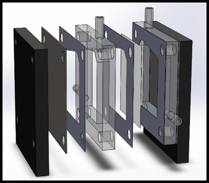
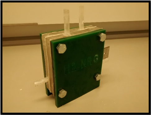
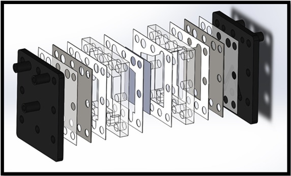
The device cross-section measures 100 mm x 100 mm and consist of two electrodes separated by two 12 mm acrylic spacers, silicon sealing gaskets, and a central Zirfon membrane (Agfa Zirfon Perl UTP 500 Separator Membrane). Electrolyte is fed into the cell via 8 mm diameter piping running through the side of the acrylic spacers, with produced gases exiting through 8mm outlets at the top of the spacers. The total working surface area for the electrodes is measured as 36 cm2, and the width of the gaskets and Zirfon membrane are assumed to be negligible. The standard alkaline electrolyser cell consists of the following components:
The device cross-section measures 100 mm x 100 mm and consist of two electrodes separated by two 12 mm acrylic spacers, silicon sealing gaskets, and a central Zirfon membrane (Agfa Zirfon Perl UTP 500 Separator Membrane). Electrolyte is fed into the cell via 8 mm diameter piping running through the side of the acrylic spacers, with produced gases exiting through 8mm outlets at the top of the spacers. The total working surface area for the electrodes is measured as 36 cm2, and the width of the gaskets and Zirfon membrane are assumed to be negligible. The standard alkaline electrolyser cell consists of the following components:
- 2 x Stainless steel (100 mm x 100 mm) electrodes
- 2 x Acrylic spacers (100 mm x 100 mm x 12 mm)
- 4 x Silicon gaskets (≈0.2 mm compressed)
- 4 x M8 nylon compression bolts with nuts
- 2 x 8 mm electrolyte feed tubes
- 2 x 8 mm gas outlet tubes
- 2 x 12 mm acrylic end plates
Experimental Methodology
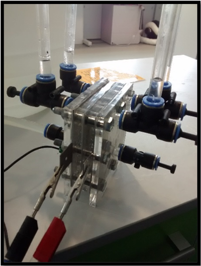
All bench scale devices being studied were connected sequentially to a reservoir containing 20 L of 0.1 M NaOH so that the volume of the reservoir was far in excess of the volume of the cell. A low concentration of electrolyte was used as the experiment was to compare both electrolysers. In a commercial operation higher concentration would be used however for the comparison this was deemed unnecessary. It is a reasonable conclusion that an increase in concentration will improve both designs performance however the trend will remain the same. The large volume of electrolyte was to ensure that the concentration of the electrolyte would not experience significant deviation throughout the course of experiments. During operation, the produced gases were vented to the atmosphere, flow through the cell was provided by gas lift and the cells were operated at room temperature.
All bench scale devices being studied were connected sequentially to a reservoir containing 20 L of 0.1 M NaOH so that the volume of the reservoir was far in excess of the volume of the cell. A low concentration of electrolyte was used as the experiment was to compare both electrolysers. In a commercial operation higher concentration would be used however for the comparison this was deemed unnecessary. It is a reasonable conclusion that an increase in concentration will improve both designs performance however the trend will remain the same. The large volume of electrolyte was to ensure that the concentration of the electrolyte would not experience significant deviation throughout the course of experiments. During operation, the produced gases were vented to the atmosphere, flow through the cell was provided by gas lift and the cells were operated at room temperature.
All electrical measurements of the cell designs were carried out with the use of an Ivium-n-Stat potentiostat multi-channel electrochemical analyser; this allowed for accurate control of the voltage supplied to the cell, as-well as for accurate measurements of the current running through the cell. Each cell’s electrical characteristics were tested by applying a voltage ramp in incremental steps of 0.5 V for 30 seconds from 0 V to 5 V. The Ivium-n-Stat took current readings every 0.5 seconds, giving 60 current readings per voltage step. The raw data was analysed using a MATLAB script, selecting the last 40 readings for each step, to form an average current value for each voltage value. This method was used to reduce experimental inaccuracies caused by the initial charging of the electrode plates when the voltage increased. The refined data was then used to plot I-V curves for each cell design, allowing for the resistance and minimum running voltages to be determined, and for direct comparison of each cell’s electrical characteristics. The average current data produced by the MATLAB script was further used to determine hydrogen production rate against both spacer size and applied voltage across the cell. To monitor the long-term performance of the devices; each cell was also run at a constant 3 V for 24 hours, with current measured every 5 seconds. Thus, any variation in performance over time was investigated and enough time was allowed for leakage from the cell to become evident.
Results and Discussion
Original Water Splitting Cell
The original water splitting device was based on previous work by Passas, [18] and had several drawbacks that were to be addressed in subsequent redesigns. During operation, the cell experienced a significant amount of leakage, and it was necessary to place the electrolyser in drip tray to contain the leaking electrolyte. The electrolyte leakage was most notable from the mating surfaces of the cell components (the face seals between gaskets, spacers and electrodes); although additional leakage was observed from the feed tubes into the spacers. Despite the use of silicon gaskets, it was found that the nylon bolts were not capable of supplying adequate compression to form a seal between component surfaces without failing. During previous investigations involving a multi-cell con Figure uration, [18] the nylon bolts were unable to adequately support the weight of the cells at the centre of the stack, causing them to sag and leak. In order to reduce leakage, the nylon bolts were replaced with stronger, steel bolts. However, to avoid the electrode shorting across the steel bolts, it was necessary to cover the threads in heat-shrink to act as an insulator where they might contact the electrodes. Changing the material of the compression bolts significantly reduced the rate at which electrolyte leaked from the cell. However, although adequate compression was applied to the corners of the cell frame, it was found that this compression was not spread uniformly across the edges of the cell as the cell is only bolted at the corners, causing the end plates and electrodes to buckle along the centre of each edge, and thus providing an inadequate seal.
The original water splitting device was based on previous work by Passas, [18] and had several drawbacks that were to be addressed in subsequent redesigns. During operation, the cell experienced a significant amount of leakage, and it was necessary to place the electrolyser in drip tray to contain the leaking electrolyte. The electrolyte leakage was most notable from the mating surfaces of the cell components (the face seals between gaskets, spacers and electrodes); although additional leakage was observed from the feed tubes into the spacers. Despite the use of silicon gaskets, it was found that the nylon bolts were not capable of supplying adequate compression to form a seal between component surfaces without failing. During previous investigations involving a multi-cell con Figure uration, [18] the nylon bolts were unable to adequately support the weight of the cells at the centre of the stack, causing them to sag and leak. In order to reduce leakage, the nylon bolts were replaced with stronger, steel bolts. However, to avoid the electrode shorting across the steel bolts, it was necessary to cover the threads in heat-shrink to act as an insulator where they might contact the electrodes. Changing the material of the compression bolts significantly reduced the rate at which electrolyte leaked from the cell. However, although adequate compression was applied to the corners of the cell frame, it was found that this compression was not spread uniformly across the edges of the cell as the cell is only bolted at the corners, causing the end plates and electrodes to buckle along the centre of each edge, and thus providing an inadequate seal.
The standard cell arrangement employed separate electrolyte feed and gas exit tubes for each compartment. Using this construction method imposed limitations on the manufacturing and performance of the device. To achieve this design, it was necessary to drill 8 mm holes laterally through the side and top of each cell spacer and install 8 mm Outer Diameter acrylic tube stubs bonded in place using acrylic adhesive (Tensol 12). This arrangement presents challenges to rapid component production and assembly slowing down the manufacturing rate of the electrolysis stacks and it also adds to the number of joints in the cell that required sealing exacerbating the issue of electrolyte leakage. The 8 mm tubes, with an internal diameter of 4 mm, provided significant restriction to the escape of gases produced within the cell. Most significantly, such a design made it impossible to reduce the width of each spacer below 12 mm. As transportation resistances are known to decrease relative to decreasing cell widths for finite-gap cells [14,18] improvements in cell efficiencies and rates of production are difficult to realize with the current design.
Geometry redesign
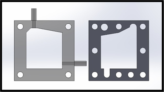
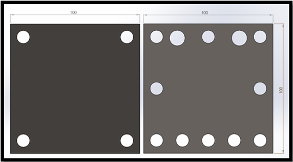
The cell design was initially modified to allow for compression bolts to run through the centre of the cell edges, as in Figure 3. As expected, this provided a more uniform compression distribution across the cell, eliminating the bowing of the cell electrodes previously observed. Despite elimination of leakage from between component mating surfaces, a small, but noticeable amount of leakage was still present from the seal between the feed in tubes and acrylic spacers; as each cell required four feed and exhaust tubes, a device incorporating stacked cells would exhibit a significant amount of leakage. To eliminate leakage from the joint where the tubes attached, a redesign of the cell geometry was proposed. The next iterative step was to design a cell spacer that did not require the use of laterally mounted feed tubes. This was achieved by incorporating a 12 mm diameter gas collection and 10 mm diameter electrolyte feed manifold into the spacer. Separate manifolds were provided for both the oxygen and hydrogen gas that ran axially above the cell and electrolyte feed manifolds running below the cell.
The cell design was initially modified to allow for compression bolts to run through the centre of the cell edges, as in Figure 3. As expected, this provided a more uniform compression distribution across the cell, eliminating the bowing of the cell electrodes previously observed. Despite elimination of leakage from between component mating surfaces, a small, but noticeable amount of leakage was still present from the seal between the feed in tubes and acrylic spacers; as each cell required four feed and exhaust tubes, a device incorporating stacked cells would exhibit a significant amount of leakage. To eliminate leakage from the joint where the tubes attached, a redesign of the cell geometry was proposed. The next iterative step was to design a cell spacer that did not require the use of laterally mounted feed tubes. This was achieved by incorporating a 12 mm diameter gas collection and 10 mm diameter electrolyte feed manifold into the spacer. Separate manifolds were provided for both the oxygen and hydrogen gas that ran axially above the cell and electrolyte feed manifolds running below the cell.
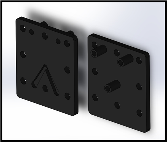
The redesigned end plates incorporated 12 mm diameter tubing that allowed for the extraction of gases and for electrolyte to be fed into the cell, as seen in Figure. 5. 8 mm wide channels were etched into the rear-side of the end plate to allow electrolyte to flow from the inlet tube to the electrolyte manifold incorporated into the cell.
Minor modification was also required of the electrodes, this consisted of additional drilling through the plate to allow for mass flow through the manifolds, likewise, the sealing gaskets were modified to have an identical cross-section to the modified spacer.
Operation of the redesigned cell verified the concept of using axial manifolds for gas removal and supplying electrolyte to the cell. The feed and exhaust tubes showed no visible leakage during operation, however, after an extended period, white precipitate formed around the tube joints, showing that although leakage was greatly reduced, it was not eliminated. Additionally, the incorporation of the gas manifolds into the cell wall provided a much greater area available for the product gases to escape from the cell, thereby reducing gas build-up within the cell at elevated current densities. The cross-section of the redesigned cell frame was kept at 100 mm x 100 mm, however the working surface-area was marginally increased to 37 cm2 while still allowing a 5 mm width at the mating faces to ensure adequate sealing.
Cell comparison
The revised design was used to produce a cell with modified 12 mm spacers. This allowed for the direct comparison of the performance of the original and modified 12 mm cells using the Ivium-n-Stat.
The revised design was used to produce a cell with modified 12 mm spacers. This allowed for the direct comparison of the performance of the original and modified 12 mm cells using the Ivium-n-Stat.
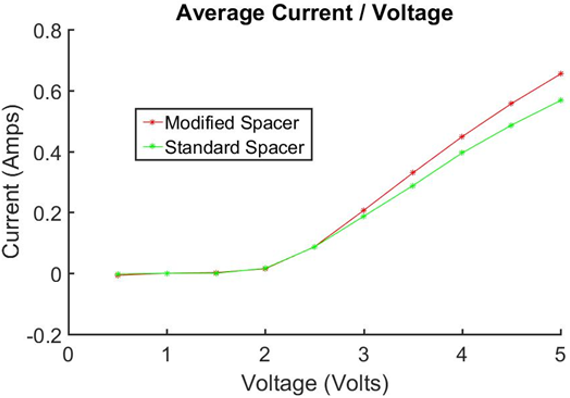
Figure 7: Average Current vs. Voltage for 12 mm spacers. Comparison at same concentrtiuon of electrolyste.
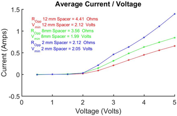
Direct comparison of both cells showed the resistance of both cells to be comparable, with slightly reduced resistance for the redesigned cell. However, this can be attributed to the slightly larger surface area of the redesigned cell, as transportation resistances are inversely proportional to surface area in an electrolysing cell. [19]
Assuming there are no parasitic reactions, and under standard conditions, the energy content of the hydrogen produced by the electrolyser can be calculated using Equation 1:
Where: I is the current through the cell, F is Faraday’s constant (96,485 A.s mol-1), ncell is the number of cells, t is the time (s), and ????????c° is the enthalpy of combustion (286 kJ mol-1).
At 3 V the standard cell and modified cell were found to be able to produce 998J (0.28 Wh) and 1100 J (0.31 Wh) respectively, while electrical power consumption was 0.56 Wh and 0.62 Wh respectively, with both cells running at an efficiency of ≈50%. This demonstrates that the change in the geometry of the cell and corresponding gas/electrolyte conduits does not have a significant effect on the efficiency.
From direct comparison of the two designs and observing their operation over an extended period, it was found that the modified, axial-flow cell was a more suitable and reliable design for use in a commercially viable water splitting device. Furthermore, due to the side-mounted tubing, the width of the original cell spacers was constrained to a minimum of 12 mm, however the redesigned cell had no such limitation. Therefore, further investigation was carried out to assess the performance of cells with reduced electrode separation distances.
Cell width reduction
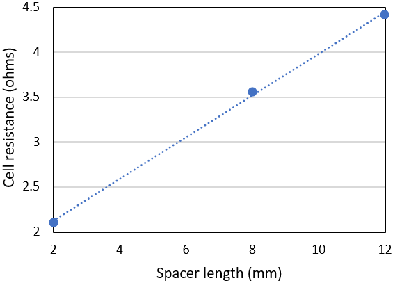
Two more modified spacers were employed in the electrolyser that were of reduced thickness relative to the original 12 mm spacer. The result was two new electrolysers where the cell gap either side of the Zirfon membrane was 8 mm and 2 mm respectively. A direct comparison was made between the cells using the Ivium-n-Stat. As shown in Figure. 10, it was found that the resistance of the cell dropped with a reduction in spacer width. The resistance of the cell incorporating the 2 mm spacers was 52% lower than the equivalent 12 mm cell. Analysing the results further showed a clear linear relation between cell width and cell resistance.
Two more modified spacers were employed in the electrolyser that were of reduced thickness relative to the original 12 mm spacer. The result was two new electrolysers where the cell gap either side of the Zirfon membrane was 8 mm and 2 mm respectively. A direct comparison was made between the cells using the Ivium-n-Stat. As shown in Figure. 10, it was found that the resistance of the cell dropped with a reduction in spacer width. The resistance of the cell incorporating the 2 mm spacers was 52% lower than the equivalent 12 mm cell. Analysing the results further showed a clear linear relation between cell width and cell resistance.
The rate at which hydrogen is produced within the electrolyser is dependent on the current through the cell. Again, assuming no parasitic side reactions, the rate of hydrogen production can be calculated using equation 2:
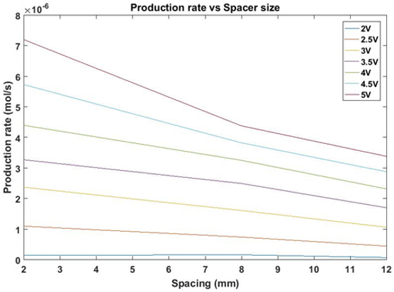
Based on the observed variation in cell resistance with cell gap length and using a MATLAB script, the rate of hydrogen production was calculated as a function of cell-gap in increments of 1 mm from 2 to 12 mm at a range voltages from 2 to 5 V in 0.5 V steps, as shown in Figure 11.
From our results, we can determine that the rate of production increases for a given voltage as cell gap size decreases. This result has important practical implications; in commercial use, the operating voltage applied across a water-splitting cell is chosen as a compromise between efficiency and rate of hydrogen production, as the energy efficiency of a cell at a given voltage is described as:
Where 1.23 V is the total reversible cell voltage.
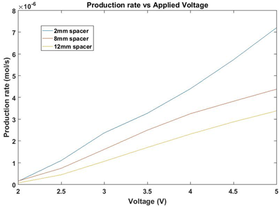
The implementation of a thinner cell allows for a lower voltage, and therefore greater efficiency, to produce the same quantity of hydrogen than a wider cell of identical design, as shown in Figure 12.
The implementation of a thinner cell allows for a lower voltage, and therefore greater efficiency, to produce the same quantity of hydrogen than a wider cell of identical design, as shown in Figure 12.
Manufacturing and cost considerations
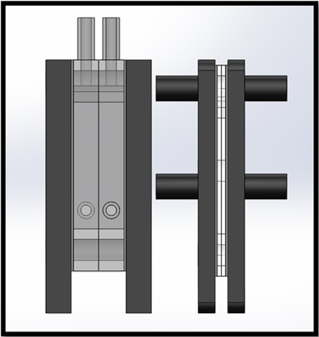
The incorporation of 2 mm spacers into the cell design has additional benefits when considering its suitability for use in a functional water splitting device. Clearly, the use of thinner spacers has cost Saving benefits, with the amount of acrylic (or other spacer material) required to produce a unit cell reduced by over 83%; at the time of writing, the material cost of the acrylic per cell is £0.24 and £1.58 for a 2 mm cell and 12 mm cell respectively. The use of axially mounted tubing as seen in Figure 14. Further reduces the amount of piping require for multi-cell electrolysers. The thinner, modified cell design also significantly cuts manufacturing time, as the use of thinner sheet acrylic allows for laser cutting tools to produce spacers more rapidly, with the available equipment for this study able to produce five 2 mm spacers in the time taken to cut a single 12 mm spacer; added to this the requirement that the original spacer had to be drilled and tubing glued in place, it is clear that an optimized cell can be produced in a fraction of the time of the standard cell. Further reduction sees the replacement of the acrylic 2 mm spacer and both gaskets with a single sheet of 2 mm butyl rubber, thus moving closer to a commercial design. The removal of internal acrylic not only saved cost but improves in the chemical resistance of the overall water lifting device as well as reducing the number of parts significantly leading towards a device that can be much easier to manufacture.
The incorporation of 2 mm spacers into the cell design has additional benefits when considering its suitability for use in a functional water splitting device. Clearly, the use of thinner spacers has cost Saving benefits, with the amount of acrylic (or other spacer material) required to produce a unit cell reduced by over 83%; at the time of writing, the material cost of the acrylic per cell is £0.24 and £1.58 for a 2 mm cell and 12 mm cell respectively. The use of axially mounted tubing as seen in Figure 14. Further reduces the amount of piping require for multi-cell electrolysers. The thinner, modified cell design also significantly cuts manufacturing time, as the use of thinner sheet acrylic allows for laser cutting tools to produce spacers more rapidly, with the available equipment for this study able to produce five 2 mm spacers in the time taken to cut a single 12 mm spacer; added to this the requirement that the original spacer had to be drilled and tubing glued in place, it is clear that an optimized cell can be produced in a fraction of the time of the standard cell. Further reduction sees the replacement of the acrylic 2 mm spacer and both gaskets with a single sheet of 2 mm butyl rubber, thus moving closer to a commercial design. The removal of internal acrylic not only saved cost but improves in the chemical resistance of the overall water lifting device as well as reducing the number of parts significantly leading towards a device that can be much easier to manufacture.
The total footprint of the optimized electrolyser is dramatically reduced by the incorporation of 2 mm spacers. For a single cell, the total length, including end plates was reduced from 50 mm to 24 mm. Furthermore, when the optimized design is used to construct multi-cell stacks, the space-saving benefits of the optimized cell are even more apparent, as seen in Figure 16. With the length of a six-cell stack is 52 mm for the optimized design compared to 180 mm for the equivalent six-cell standard stack.
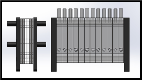
Figure 16: Comparison of six cell stacks incorporating 2 mm cells (left) and standard 12 mm cells (Right).
Conclusion
The original water splitting device underwent a considerable redesign to reduce electrolyte leakage from the cell. Improving cell compression and replacing the side-mounted feed/gas tubes with integrated manifolds was found to produce a cell with negligible leakage. A significant consequence of this redesign was the ability to further reduce the width of the cell. In doing so, a massive reduction in the cell resistance was achieved, improving the efficiency and production rates of the device. Additionally, the optimized device also benefited from reduced manufacturing time and costs.
The modular nature of the optimized water splitting device proposed by this study allows for the number of cells in a water splitting stack be chosen so as Hydrogen can be produced at a maximum efficiency for a given power source. This low-cost high-efficiency electrolyser stack opens the door to energy storage from intermittent renewable energy sources helping to balance the supply and demand on the national power infrastructure.
Acknowledgements
Stephen Mandale and Katherine Glover are funded by the RICE project and would like to thank the Welsh Government (EU European Regional Development Fund) for funding the RICE (Reducing Industrial Carbon Emission) project (Grant Number: 81435).
Stephen Mandale and Katherine Glover are funded by the RICE project and would like to thank the Welsh Government (EU European Regional Development Fund) for funding the RICE (Reducing Industrial Carbon Emission) project (Grant Number: 81435).
References
- Turner, J. (1999). A realizable renewable energy future. Science 285, 687.
- Marc Beaudin, H. Z. (2010). Energy storage for mitigating the variability of renewable electricity sources. Energy for Sustainable Development 14, 302-314.
- André Pina, C. S. (2012). The impact of demand side management strategies in the penetration. Energy 41, 128-137.
- Deepak Yadav, R. B. (2020). Net energy and carbon footprint analysis of solar hydrogen production from. Applied Energy, 262.
- McDowall, W. (2006). Forecasts, scenarios, visions, backcasts and roadmaps to the hydrogen. Energy Policy 34, 1236–1250.
- Bockris, C. Y. (New York: Plenum, 1984).
- HyDeploy under way as UK’s grid-injection hydrogen pilot project. . Fuel Cells Bulletin February, 10 (2020).
- Hollmuller, P. J. (2000). Evaluation of a 5kW photovoltaic hydrogen production and storage installation for a residential home in Switzerland. International Journal of Hydrogen Energy 25, 97-109.
- Jones, D. R., Al-Masry, W. A. & Dunnill, C. (2018). Hydrogen-enriched natural gas as a domestic fuel: an analysis based on flash-back and blow-off limits for domestic natural gas appliances within the UK. Sustainable Energy & Fuels 2, 710-723.
- Mulla, R. & Dunnill, C. W. (2019). Powering the Hydrogen Economy from Waste Heat: A Review of Heat-to-Hydrogen Concepts. ChemSusChem 12, 3882-3895.
- Shiva, S. & Kumar, V. (2016). Hydrogen production by PEM water electrolysis – A review. Material Science for Energy technologies 2, 442-454.
- Widera, B. (2020). Renewable hydrogen implementations for combined energy storage, transportation and stationary applications. Thermal Science and Engineering Progress 16.
- Gannon, W. J. F. & Dunnill, C. W. (2019). Raney Nickel 2.0: Development of a high-performance bifunctional electrocatalyst. Electrochimica Acta 322, 134687.
- Zeng, K. Z. (2010). Recent progress in alkaline water electrolysis for hydrogen production and applications. . Progress in energy and combustion science 36, 317.
- Phillips, R. & Dunnill, C. W. (2016). Zero Gap Alkaline Electrolysis Cell Designs for Renewable Energy Storage as Hydrogen Gas. RSC Advances 6, 100643.
- Phillips, R., Edwards, A., Rome, B., Jones, D. R. & Dunnill, C. W. (2017). Minimising the ohmic resistance of an alkaline electrolysis cell through effective cell design. International Journal of Hydrogen Energy 42, 23986-23994.
- Gannon, W. J. F., Jones, D. R. & Dunnill, C. W. (2019). Enhanced Lifetime Cathode for Alkaline Electrolysis Using Standard Commercial Titanium Nitride Coatings. Processes 7, 112.
- Passas, G. & Dunnill, C. W. (2015). Water Splitting Test Cell for Renewable Energy Storage as Hydrogen Gas. Journal of Fundamentals of Renewable Energy and Applications 5, 188.
- Godula-Jopek, A. & Stolten, D. (Berlin: John Wiley and Sons, 2015).
Citation: Adam Rearden, Stephen Mandale, Katherine Glover, Robert Phillips and Charles W. Dunnill. (2020). Optimizing the Design of an Alkaline Water Splitting Device Test cell for Renewable Energy Storage as Hydrogen. Archives of Chemistry and Chemical Engineering 2(1). DOI: 10.5281/zenodo.3964220
Copyright: © 2020 Charles W. Dunnill. This is an open-access article distributed under the terms of the Creative Commons Attribution License, which permits unrestricted use, distribution, and reproduction in any medium, provided the original author and source are credited.


