Research Article
Volume 1 Issue 2 - 2019
Installation and Design of a New Wind Tunnel for Measurement of Vertical Axis Wind Turbines (VAWT)
1University of Applied Sciences Saarbrücken, Goebenstraße 40, 66117 Saarbrücken Germany.
2University of Applied Sciences Würzburg-Schweinfurt, Ignaz-Schön-Straße 11 97421 Schweinfurt, Germany.
3Helmut-Schmidt-Universität/Universität der Bundeswehr Hamburg, Holstenhofweg 85, 22043 Hamburg, Germany.
2University of Applied Sciences Würzburg-Schweinfurt, Ignaz-Schön-Straße 11 97421 Schweinfurt, Germany.
3Helmut-Schmidt-Universität/Universität der Bundeswehr Hamburg, Holstenhofweg 85, 22043 Hamburg, Germany.
*Corresponding Author: Frank Ulrich Rückert, University of Applied Sciences Saarbrücken, Goebenstraße 40, 66117 Saarbrücken Germany.
Received: November 03, 2019; Published: November 13, 2019
Abstract
Over the past few years, the University of Applied Sciences in Saarbrücken (htw saar) has carried out intensive research into small scale wind turbines, especially in Vertical Axis Wind Turbine (VAWT). The well-known problem with the design of these types are, that the efficiency is about 25% lower as comparable horizontal axis wind turbines. Very small VAWTs have beside this lower efficiency also the problem that they did not start to run automatically. They must be electrically driv-en to start, which is due to design problems. The reason was identified by our team with numerical simulations of detachment behavior at the blades. However, this can only be clarified by means of detailed measurement.
In order to compare simulations, and investigate turbines behavior more deeply, a new wind tunnel was constructed from scratch at htw saar. The so-called Göttinger design was chosen as type of construction, which means that air circulates inside in a closed setup. Dimensions of the tunnel are 12 m x 3.5 m x 2m. Air is driven by a 75 kW rotor placed on upper side. The nozzle diameter is about 1.6 x 1.6 meter for the first test section setup. The VAWT can be placed in this position. Access points are positioned for temperature, pressure and velocity flow examinations. An addi-tional heat absorber is used to control the air temperature. Two windows posi-tioned inside the nozzle chamber can be used to visualize turbulence effects and enable the qualitative measurement of the spatial position and strength of com-pressible air vortices with a high-speed camera. There is currently no alternative test rig know for these kind of experiments.
Thus, qualitative and quantitative behavior of the VAWT can be examined. The in-vestigation in the transonic wind tunnel, as well as the adjustment with simulations of the VAWT will be used for validation and further design development.
Key words: Small wind turbine; Computational fluid dynamics (CFD); Finite element analysis (FEA); Experimental investigations; Low speed wind tunnel; Additive manufactur-ing (AM); Design optimization; ANSYS CFX; Vertical small wind turbine (VAWT); Fused deposition modeling (FDM)
Introduction
Wind energy as a source of renewable energies has become a daily encounter. Therefore, the market of small energy conversion facilities has grown and given the innovative role of Vertical Axis Wind Turbines (VAWT). This motivated us in the year 2012 to start developing an in-house wind tunnel at University of Applied Sci-ences Saarbrücken.
Antiquity and History
Now and in future, engineers and designers seem to continue to be challenged. Alt-hough Albert Betz has already proven that the wind is capable of producing a max-imum of 59.2% of its power, this fact does not prevent from getting as close as possible to this maximum by increasing efficiency in the energy-converting system [1]. In Figure 1 you can see Albert Betz in in the wind lab at the Aerodynamische Versuchanstalt, next to the wind tunnel and the three-component scale, the measur-ing section with rectangular wing.
Now and in future, engineers and designers seem to continue to be challenged. Alt-hough Albert Betz has already proven that the wind is capable of producing a max-imum of 59.2% of its power, this fact does not prevent from getting as close as possible to this maximum by increasing efficiency in the energy-converting system [1]. In Figure 1 you can see Albert Betz in in the wind lab at the Aerodynamische Versuchanstalt, next to the wind tunnel and the three-component scale, the measur-ing section with rectangular wing.
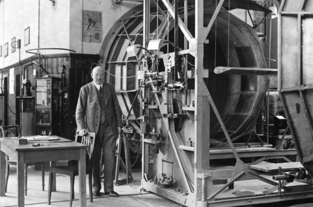
Figure 1: The inventor Albert Betz in front of his wind tunnel in Göttingen (1930); inside the nozzle test region a wing airfoil can be seen [34].
To improve the design of wings for windmills, Albert Betz developed a special wind tunnel for the examination of an airfoils under different Reynolds numbers and constructed it at the research center in Göttingen. Goal was to reach Reynolds similarity even for small scale models of the airfoils.
The design process proposes a new set of geometry parameters for the better ful-filment of these objectives, which closes the cycle. The lift and drag coefficients to improve the design of new windmill wings are not only dependent on angel of at-tack, but also on the Reynolds number. Which is defined as follows:
Re = (v-l)
ν (1)
Re = (v-l)
ν (1)
The Reynolds number Re is the quotient of friction forces to inertial forces in the flow and characterizes the flow state [14], where v is the incident flow velocity, l the characteristic length (here the profile chord length) and ν the kinematic viscosity of air at given temperature. So temperature is also major parameter for further scientific examinations.
In the year 2012 the engineer and scientist Tobias Müller got his call for an endowed professorship in wind energy at University of Applied Sciences Saarbrücken and after several proposals he and his work group decided to design a new type of wind tunnel with Göttinger design in-house our institute.
The best possible adaptation of the further design made by Albert Betz to the available wind speeds and Reynolds numbers is therefore of paramount importance. This requires knowledge of all forces acting on the rotor blade. The demonstration wind tunnel at the htw saar offers the possibility of aerodynamically investigating different rotor designs and blade profiles at varying inflow speeds on a handy scale in order to obtain meaningful information for larger applications. The whole design chain from computational fluid dynamics simulation, design construction, fused deposition modeling (FDM) of the airfoils as well as testing is given in our laboratory [31]. Further the plan was to found an open workspace for students and scientific staff to meet and work together on projects as kind of an inverted class room as described in [32].
A New Concept for Göttinger Design
Main data for the setup of the new concept for Göttinger design is shown in Figure 2 is given at Lehser-Pfeffermann., et al. [1]. Flow simulations (computational fluid dynamics CFD) also provide important conclusions on the behavior of a wind turbine and its maximum performance and build the first step in the design process.
Main data for the setup of the new concept for Göttinger design is shown in Figure 2 is given at Lehser-Pfeffermann., et al. [1]. Flow simulations (computational fluid dynamics CFD) also provide important conclusions on the behavior of a wind turbine and its maximum performance and build the first step in the design process.
In frame of this work, a constant temperature is essential inside the channel therefor an additional heat exchanger was added to the earlier design as could be seen in Figure 2. The velocity profile inside nozzle region should be also constant. The Reynolds number is controlled by changing the inflow velocity around a ventilator. Strains inside the fluid should be controlled for each Reynolds number and provide information on the aerodynamic behavior at different wind speeds. The inflow wind speed variation is between a minimal velocity of v = 2.0 m/s and a maximum velocity of vmax = 12.5 m/s. To get stable conditions inside the nozzle region where the objects for the experiments are placed a laminar fluid flow should be reached by small baffles in the corner regions of the channel and by screens and an additional honeycomb in a settling chamber upstream the nozzle region. Pope et al described methods do dimension such tunnel parts [29].
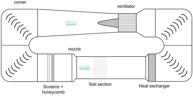
Figure 2: New concept for the wind tunnel with Göttinger design at the University of Applied Sciences in Saarbrücken (htw saar).
To achieve the described improvement of the ventilator, mainly focusing on the variation of blade characteristics associated with the maximization of the energy output, different approaches have already been made. As can be seen from Figure 2 the guidance of the fluid at the corners of the tunnel, as well as the swirl introduced by the ventilator can lead to high turbulences inside the tunnel, so the flow field has to be calculated with a Computational Fluid Dynamics (CFD) approach, the latter applied it alongside the channel flow. Difficulties in the design can also be the location of the ventilator at the top of the rig, because this can induce stresses of the full structure. So a Finite Element Analysis (FEA) has to be done.
Mathematical Models, Numerical Simulation and Construction
To improve the design and start construction Müller started in the year 2012 with examination of the corner of the channel and simulation of the flow field inside the channel (see Figure 2). The flow has to be assumed to be three-dimensional and Computational Fluid Dynamics (CFD) analysis was performed on the general-purpose code ANSYS Fluent [17], applying the Finite Volume Method (FVM) for discretizing the governing differential equations. Given the scarcely used method of CFD simulation with solving the Navier-Stokes equations, these settings and boundary conditions are essentially needed for comparison design variants and optimize the flow inside the tunnel. Looking at the former listed works describing construction of test rigs like described those details of the mathematical and numerical formulation adequately [11-13].
To improve the design and start construction Müller started in the year 2012 with examination of the corner of the channel and simulation of the flow field inside the channel (see Figure 2). The flow has to be assumed to be three-dimensional and Computational Fluid Dynamics (CFD) analysis was performed on the general-purpose code ANSYS Fluent [17], applying the Finite Volume Method (FVM) for discretizing the governing differential equations. Given the scarcely used method of CFD simulation with solving the Navier-Stokes equations, these settings and boundary conditions are essentially needed for comparison design variants and optimize the flow inside the tunnel. Looking at the former listed works describing construction of test rigs like described those details of the mathematical and numerical formulation adequately [11-13].
Comparing different design variants, mathematical formulation of a two-equation turbulence model, which is more precise, and not only used different angles of attack but the approach velocity magnitude was varied as well and gives well predictability for the rigs function [13].
In a first step in formulation of a mathematical model of the wind tunnel, the transport equations are established, discretized and solved in numerical flow simulation. Therefore it was possible to generalize these transport equations as follows [15] for a dependent variable Φ, which is replaced by the flow size that is currently of interest. The variable Φ represents in this case the velocities, turbulence-quantities as well as temperature fields inside the wind tunnel, which is balanced by the following formula. If any transport equation is to be adapted to the general form, all terms that do not belong to convection or diffusion are gathered in the source term [15].
Here Γ is the diffusion coefficient inside the air field. The convective terms are dis-cretized in ANSYS Fluent by a formally third-order accurate Quadratic Upwind In-terpolation (QUICK) scheme [15, 17] for the Navier-Stokes Equations and a second-order upwind discretization scheme (UDS) [15, 17]. After the transport equations have been established, they are discretized to solve the mathematical formulation numerically. The total volume of the wind tunnel has to be divided into small, dis-crete control volumes. These are also called control volumes or cells [12, 15, 16]. Flow is modelled within a Reynolds Averaged Numerical Simulation (RANS) ap-proach [18], where the time-averaged equations are solved for the time-averaged variables in steady-state.
Turbulence is modelled by a two-equation turbulence model, the Shear Stress Transport (SST) model [17, 21], which performs quite reliably especially for wall-driven turbulent flows with potential to predict transitional effects [21]. In this work, the turbulent kinetic energy k and the inverse time ω are used to describe the turbulent linear dimension L. The conservation equation for kinetic energy is modi-fied as follows [16]. These uncertainties are know from literature [19].
Based on CFD results of the flow field Müller started Finite Element Analysis (FEA) of the full size wind tunnel as described in [33]. FEA was performed for the full tunnel except of the nozzle region (see Figure 2) because this test region was planned to be produced by another material (here: wood and PMMA), for easier installation of measurement equipment and better deconstruction of the test objects (e.g. VAWT).
FEA is one of the most popular mechanical engineering applications offered by existing CAD systems. FEA tool is the mathematical idealization of real system geometry and is used to examine oscillation based on fluid motion and ventilator vibrations that are induced to the material of the channel walls. Also the stiffness of the construction was examined. With the use of this computer based technique it breaks geometry into elements, the so called discretization and links a series of equations to each and solves the equations simultaneously to evaluate the behavior of the entire system. The method is analogues to the fluid dynamic simulation. The Simulation tool ABAQUS FEA [33] was used to perform the simulation. It is used in situations where geometry and material properties are complicated and exact ana-lytical solution is difficult to obtain.
Most often used for structural, thermal, fluid analysis, but widely applicable for other type of analysis and simulation. A finite element mesh for the analysis was generated for the tunnel by using standard command in the three dimensional form by using hexahedral elements tetrahedral finite elements and then the meshed com-ponent is tested for quality of mesh. In Figure 3 the geometric model and the FEA results from the tool ABAQUS are presented. It can be observed, that high magni-tudes of deformations at the walls can be found near the position of the ventilator. From the FEA, the various stress and deformation values have been found that where induced by the flow field of the air and corresponding to the oscillations that come from the ventilator. Also high magnitudes of stress can be found near the engine of the ventilator upstream as well as downstream. This is because of the introduced forces from the ventilator to the whole structure of the channel. The maximum on deformation acting on ventilator region in real working condition was found to be 5.646 and nearly 0 as minimum.
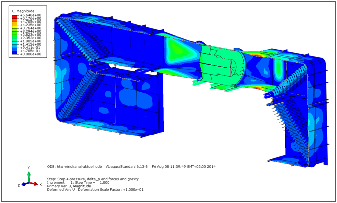
Figure 3: Finite element simulation of the full metal construction of the new wind tunnel design; high regions of deformable magnitudes near ventilator region.
Another problem that was predicted with the help of FEA simulation was the noise development during operation. The different speeds excite all frequencies and thus all natural frequencies of the system. If such an excitation of the natural frequency takes place on the large-surface thin-walled side surfaces of the tunnel, the resulting oscillation amplitudes are quite large. This results in a high noise level. In order to prevent this, or at least to reduce it, stiffeners were attached to the channel walls. This results in only very low vibration amplitudes as can be seen in the Figure 3.
Baffles are provided at the angles to divert the flow as seen in the positions shown in Figure 2. It results on one hand from the small installation space of the angle and on the other hand the baffles help to ensure a more even flow. Without this redirec-tion aid, the speed would increase significantly towards the outer radius due to the mass inertia. In the test section, the speed in the upper range would then be close to 0 and the maximum speed at the ground with large gradients over the test section area. To prevent this, baffles were fitted.
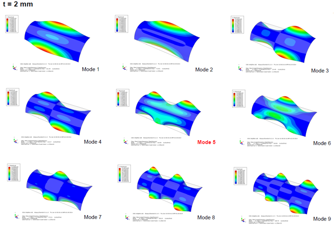
Since these plates are heavily loaded during operation and excited in different fre-quency spectra, the resulting vibration amplitudes and Eigenmodes were investi-gated with the aid of the FEA (see Figure 4). This excitation could be determined as an essential source of noise. Therefore, in addition to the variation of the sheet thickness, additional supports and stiffeners were also examined. In the final con-figuration, the amplitudes of the excited Eigenmodes are low and strong noise emission could be successfully prevented.
In Figure 4 different modes for the fins in the corners of the channel are presented, which were shown to perform quite reliably especially for wall-driven turbulent flows with potential to predict transitional effects [21]. In this work, the turbulent kinetic energy k and the inverse time ω are used to describe the turbulent linear dimension. The conservation equation for kinetic energy is modified as follows [16]. Based on FEA analysis the stresses are examined and the geometry of the fins have been optimized to reduce oscillations.
So mathematical modelling was done for fluid flow (CFD) and for stresses as well as oscillation (FEA), but was not done for heat transfer inside the channel. It will be shown in the next chapter that forbearance of this fact guided us to some trouble and caused a delay in our project management of about 1.5 years.
Installation of the New Wind Tunnel
After completing the design concept of the full scale wind tunnel as described be-fore the installation of the new wind tunnel started in the year 2013 with project management of the construction of the tunnel and ordering of the different parts. Luckily it was possible to construct the tunnel inside the new technical laboratory tract of our school called Technikum (German for: technical center). The project started with the layout of the fluid energy machine, the ventilator.
After completing the design concept of the full scale wind tunnel as described be-fore the installation of the new wind tunnel started in the year 2013 with project management of the construction of the tunnel and ordering of the different parts. Luckily it was possible to construct the tunnel inside the new technical laboratory tract of our school called Technikum (German for: technical center). The project started with the layout of the fluid energy machine, the ventilator.
The 75 kW Ventilator
As first component the ventilator for the wind tunnel was ordered and delivered to our Technikum in Saarbrücken. The ventilator is shown in Fig. 5, on the left side of the figure, the stator region before the fan can be seen. On the right side of the Figure 5 the rotor is presented. It was produced in November 2014 by LTG Aktiengesell-schaft in Stuttgart and has at ventilation power of 75 kW with a maximum air vol-ume flow of 100.000m³/h.
As first component the ventilator for the wind tunnel was ordered and delivered to our Technikum in Saarbrücken. The ventilator is shown in Fig. 5, on the left side of the figure, the stator region before the fan can be seen. On the right side of the Figure 5 the rotor is presented. It was produced in November 2014 by LTG Aktiengesell-schaft in Stuttgart and has at ventilation power of 75 kW with a maximum air vol-ume flow of 100.000m³/h.

Figure 5: Design of the new 75 kW electric ventilator; left side: stator region after the ventilator rotor; right side: rotor and electric unit.
The high energy demand of about 75 kW leaded to some additional design considerations, because the electric energy will be converted to heat and has to be discharged from the process, because Göttinger design always demands a cycle air flow. Because the heat exchanger was not plant in the earlier design additional cost had to be tackled. Neglecting this heat transfer problem in the first design step had to be corrected and in current design we also installed an addition heat exchanger after the test region (see also Figure 2).
The Corner Regions and the Construction
As explained before based on the FEA and CFD results, production plans were pre-pared. Taking into account the handling and better transport characteristics, the channel was divided into several segments. The individual components are assem-bled on site in the laboratory using flange connections and seals.
As explained before based on the FEA and CFD results, production plans were pre-pared. Taking into account the handling and better transport characteristics, the channel was divided into several segments. The individual components are assem-bled on site in the laboratory using flange connections and seals.
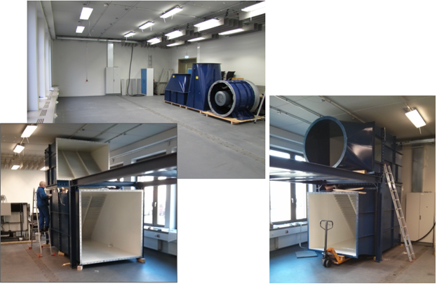
Figure 6: Corner regions with the baffles are installed in countercurrent directions in the laboratory; ventilator region is prepared to be installed at top of the frame struc-ture.
A frame structure is built up to decouple the ring excitation fan and on the basis of its own weight. The fan can then be placed on top of this as shown in Figure 6. Size of the whole test rig can be estimated by comparison with the size of our worker at the lower left side of the figure.
Nozzle Region and Heat Exchanger
After the settling chamber in downwind direction a nozzle is installed. This reduces the cross-section by a factor of 1.4 to the measuring section of 1.6m x 1.6m. In a second planned setup, the cross-section is to be reduced to 0.6m x 0.6m in order to achieve flow velocities of up to 70m/s in the measuring section.
After the settling chamber in downwind direction a nozzle is installed. This reduces the cross-section by a factor of 1.4 to the measuring section of 1.6m x 1.6m. In a second planned setup, the cross-section is to be reduced to 0.6m x 0.6m in order to achieve flow velocities of up to 70m/s in the measuring section.
The current structure of the test track consists of a frame into PMMA and wooden panels can be installed. Access to the measuring section is ensured via openings. With the transparent PMMA plates, test sequences can be observed directly and flow visualization methods can be used. Colored and controllable lighting ensures good illumination of the experimental set-up.
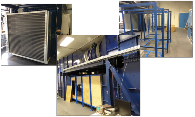
Figure 7: Construction of the nozzle region and connection in between the corner regions; material of nozzle regions is PMMA and wood for a higher flexibility; left: heat exchanger installation downstream of test section.
In order to achieve constant and adjustable temperature conditions, a heat exchang-er is subsequently installed at the measuring section. This is connected to a cooling system and equipped with a droplet separator for condensing air as shown in Fig-ure 7. The cooling system is connected to our in-house cooling system of htw saar with lowest temperatures of 7°C. A View from inside the test region for validation of an in-house developed VAWT is shown in Figure 8.
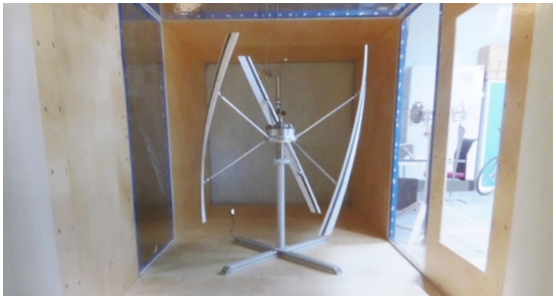
Figure 8: View from inside the test region of low speed wind tunnel at htw saar (Saar-brücken) for validation of the Vertical Axis Wind Turbine (VAWT).
First Results and Scientific Work
After commissioning, the first experimental investigations could already be carried out. A small vertical wind turbine designed by Lehser-Pfeffermann., et al. [1] was constructed. Ruffino., et al. [28, 31] previously carried out flow simulations which could be validated with the help of the experimental investigation.
After commissioning, the first experimental investigations could already be carried out. A small vertical wind turbine designed by Lehser-Pfeffermann., et al. [1] was constructed. Ruffino., et al. [28, 31] previously carried out flow simulations which could be validated with the help of the experimental investigation.
Velocity Distributions
After finishing the building process of the tunnel, the flow conditions in the measur-ing section are first determined experimentally. Calibrated Prandtl probes and hot-wire anemometers are used for this purpose. At constant temperature and fan speed, the following flow distributions result for half the test section area, as shown in Figure 8.
After finishing the building process of the tunnel, the flow conditions in the measur-ing section are first determined experimentally. Calibrated Prandtl probes and hot-wire anemometers are used for this purpose. At constant temperature and fan speed, the following flow distributions result for half the test section area, as shown in Figure 8.
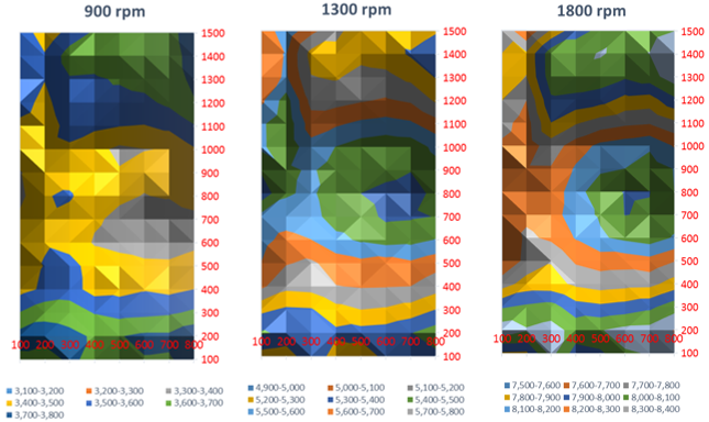
Figure 9: Measured velocity distributions (in m/s - half section area; distances in mm) inside the tunnel at 900 rpm 1300rpm and 1800rpm ventilator speed.
This results in a homogeneous velocity distribution in the center of the measuring section. Due to the contraction via the nozzle, there is a gradient to the edge of the tunnel section area with significantly increased wind speeds. The speed kit distri-butions shown have been determined directly at the nozzle. Since the test setup is located 1.5 m downstream, the gradient is significantly lower at the level of the test.
Validation for Computational Fluid Dynamics
The rotor blades for the VAWT are produced using additive manufacturing process-es. The test system can then be installed in the test section. A CFD model is also created to compare the measurements performed (cf. Ruffino., et al. [28, 31]). In each case, start-up tests of the turbine are carried out at different wind speeds.
The rotor blades for the VAWT are produced using additive manufacturing process-es. The test system can then be installed in the test section. A CFD model is also created to compare the measurements performed (cf. Ruffino., et al. [28, 31]). In each case, start-up tests of the turbine are carried out at different wind speeds.
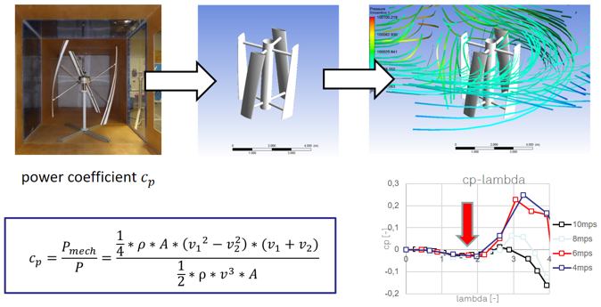
Figure 10: Comparison of lift forces over angle of attack based on computational fluid dy-namics (CFD) simulation with measurements inside the wind tunnel for better un-derstanding of design problems of the foils.
To improve geometry of the wings of vertical axis wind turbines (VAWT) several approaches have been made. While Mendez and Greiner [6] applied genetic algo-rithms (GA) and the Blade Element Momentum (BEM) theory to optimize aerody-namic aspects considering blade chord and twist angle, Kenway and Martins [7] solved the problem of optimizing a wind turbine blade by applying a multidiscipli-nary design approach as well as a gradient based optimization algorithm. Regarding the airfoil, Li., et al. [8] offered a technique to optimize the lift-to-drag ratio for 2D airfoils using response surface methods and using numerical optimization. Graaso [9] especially focused on the tip region of the blade of the airfoil design. Chen and Agarwal [10] as well as Riberio.,, et al. [11] used CFD for analysis. Benim, et al. gave a good overview over this work [4]. Also, Ju and Zhang [12].
The authors maximized the lift to drag ratio and the lift coefficients of the airfoil and with it developed an optimization procedure for wind turbine airfoils. In the given approaches for aerodynamic analysis by [8] and [10], some important details as the used turbulence model, near-wall treatment and the applied models and methods are not sufficiently addressed.
Starting Torque Problem of VAWT
Due to the small rotor diameter of 1m and the very short chord length of the blades (75mm) for dis diameter, problems arise when starting up the system. The tests at different wind speeds show that the system starts up but does not accelerate to nominal speed. It would have to be actively accelerated to nominal speed via the generator in engine operation. This behavior could be demonstrated in experiments and CFD simulations.
Due to the small rotor diameter of 1m and the very short chord length of the blades (75mm) for dis diameter, problems arise when starting up the system. The tests at different wind speeds show that the system starts up but does not accelerate to nominal speed. It would have to be actively accelerated to nominal speed via the generator in engine operation. This behavior could be demonstrated in experiments and CFD simulations.
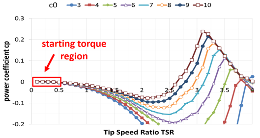
Figure 11: Results of the mathematical model for starting process of a small scale vertical axis wind turbine (VAWT) with power coefficient over tip speed ratio; critical starting torque can be identified.
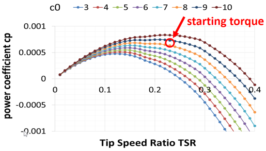
Figure 12: Details of the results of the mathematical model for starting process of a small scale vertical axis wind turbine (VAWT) with power coefficient over tip speed ra-tio; critical starting torque can be identified.
In the further course of the project, this behavior is to be further analyzed and opti-mized with the aim of accelerating the system automatically to nominal speed without additional drive at the end of the project.
Conclusions and Outlook
Tobias Müller and his team begin with a rough estimate. In Figure 13 our finished wind tunnel for the experimental investigation of small wind turbines and compo-nents of multi-megawatt machines can be seen. Our wind tunnel is developed at htw saar on its own initiative. This is refined by the use of flow simulation. A spe-cial focus is on the baffles in the angular segments of the channel.
FEA methods are used for static load-bearing capacity and noise development. Based on natural frequency simulations, the construction is stiffened in such a way that the resulting vibration amplitudes become minimal. It can also be used to pre-vent inadmissible distortion during operation.
With various screens and honeycombs laminar flow ratios within the measuring section can be implemented. Due to a specially designed heat transfer, it is also possible to carry out tests at constant temperature conditions. In the measuring section itself, visual flow investigation is possible by means of variable lighting and transparent wall elements.
After the system has been calibrated, the first tests can already be carried out on small wind turbines. The previously determined numerical simulation results are validated against measurements from our htw saar low-speed wind tunnel. With this method the rotor blades of our VAWT can be improved constructively and economically. The entire workflow of automatic design generation, simulation, additive manufacturing by FDM pressure and measurement in the low-speed wind tunnel can thus be mapped in htw wind energy lab. [31].
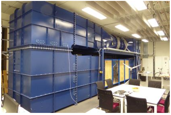
Figure 13: Full constructed wind tunnel inside wind laboratory at University of Applied Sci-ences in Saarbrücken (htw saar); open work space in front of the channel for teach-ing and students work.
Students, interns and scientists are closely involved in this by allowing the wind energy laboratory to work close to the site of the event, similar to Albert Betz. By setting up an open workspace like described in [32], close interdependence be-tween research and teaching is guaranteed.
Improvements to the existing simulation models are planned as further work. By using Large Eddy Simulation, turbulent flows can be better resolved. These meth-ods will then be used to further improve the start-up behavior of the VAWT proto-type.
One thing was not mentioned up to now. At the b/w picture in Figure 1 at the begin-ning of this paper as well as in Figure 13 at its end, there is a table with chairs in front of each wind tunnel to sit down and talk with each other. Nearly 90 years after take the open minded picture from Albert Betz we want to give an open minded work space for young millennium scientist. Also we want to thank our numerous founders for trust and especially Prof. Dr.-Ing. Friedrich Klinger from INNOWIND Forschungsgesellschaft mbH for his good advice and help.
References
- Lehser-Pfeffermann, D. (2016). Müller, T.: Development process of a vertical axis wind turbine. In: 7th world summit for small wind, Husum Germany.
- Barlow, J.; Rae, W.; Pope, A. (1999). Low-Speed wind tunnel testing. Third edition. John Wiley & Sons. New York.
- Paraschivoiu, I. (2009). Wind turbine design. Presses internationales Polytechnique, Canada.
- Benim, A.C.; Diederich, M.; Pfeiffelmann, B. (2018). Aerodynamic Optimization of Airfoil Profiles for Small Horizontal Axis Wind Turbines. Computation 6, 34.
- Alaimo, A.; Esposito, A.; Messineo, A.; Orlando, C.; Tumino, D. (2015). 3D CFD Analysis of a Vertical Axis Wind Turbine. Energies 8, 3013-3033.
- Mendez, J.; Greiner, D. (2006). Wind blade chord and twist angle optimization by using genetic algorithms. In Proceedings of the 5th Conference on Engineering Computational Technology, Las Palmas de Gran Canaria, Spain.
- Kenway, G.; Martins, J.R.R.A. (2008). Aerostructural shape optimization of wind turbine blades considering site-specific winds. In Proceedings of the Multidisciplinary Analysis and Optimization Conference, Victoria, BC, Canada.
- Li, J.Y.; Li, R. Gao, Y.; Huang, J. (2010). Aerodynamic optimization of wind turbine airfoils using response surface techniques. Proc. Inst. Mech. Eng., Power Energy 224, 827–838.
- Grasso, F. (2012). Hybrid optimization for wind turbine thick airfoils. In Proceedings of the 53rd Structural Dynamics and Materials Conference, Honolulu, HI, USA.
- Resch, M.; Currle-Linde, N.; Küster, U.; Risio, B.: A Grid Framework for Computational Mechanics Applications, Proceedings of the 2nd WSEAS Int. Conference on Applied and Theoretical Mechanics, Venice, Italy, November 20-22
- Ribeiro, A.F.P.; Awruch, A.M.; Gomes, H.M. (2012). An airfoil optimization technique for wind turbines. Appl. Math. Model, 36, 4898–4907.
- Ju, Y.P.; Zhang, C.H. (2012). Multi-point robust design optimization of wind turbine airfoil under geometric uncertainty. Proc. Inst. Mech. Eng. Part A J. Power Energy, 226, 245–261.
- Rückert, F.U.; Ströhle, J.; Sabel, T.; Schnell, U.; Hein, K. R. G. (2001). Advantages of Combining Different Grid Types for 3D Furnace Modelling, Sixth International Conference on Technologies and Combustion for a Clean Environment, Porto (Portugal), 09 - 12 July.
- Hau E. (2014). Windkraftanlagen: Grundlagen, Technik, Wirtschaftlichkeit. 5., Heidelberg: Springer-Verlag.
- Ferziger, J. H., Peric, M. (1999). Computational Methods for Fluid Dynamics; Springer; Berlin, Heidelberg, New York.
- Wursthorn, S. (2001). Numerische Untersuchung kavitierender Strömungen in einer Modellkreiselpumpe; Universität Karlsruhe, Dissertation, Karlsruhe.
- Engineering Simulations and 3-D Design Software. Available online: www.ansys.com
- Durbin, P.A.; Pettersson Reif, B.A. (2011). Statistical Theory and Modeling for Turbulent Flows, 2nd ed.; Wiley: Chichester, UK.
- Benim, A.C.; Nahavandi, A.; Syed, K. (2005).URANS and LES analysis of turbulent swirling flows. Progress in Computational Fluid Dynamics an Int. J. 5, 444–454.
- Benim, A.C.; Chattopadhyay, H.; Nahavandi, A. (2011).Computational analysis of turbulent forced convection in a channel with a triangular prism. Int. J. Therm. Sci. 50, 1973–1983.
- Menter, F.; Esch, T.; Kubacki, S. (2002).Transition modelling based on local variables. In Proceedings of the Fifth International Symposium on Engineering Turbulence Modelling and Measurements, Mallorca, Spain, 16–18 September 2002; Engineering Turbulence Modelling and Experiments 5. Rodi, W., Fueye, N., Eds.; Elsevier: Amsterdam, Netherlands,; pp. 555–564.
- Benim, A.C.; Cagan, M.; Gunes, D. (2004).Computational analysis of transient heat transfer in turbulent pipe flow. Int. J. Therm. Sci., 43, 725-732.
- Deng, G.B.; Ferry, M.; Piquet, et al. (1992). New fully coupled solutions of the Navier-Stokes equations. In Notes on Numerical Fluid Mechanics (NNFM), Proceedings of the 9thGAMM, Lausanne, Switzerland, 1991; Springer: Wiesbaden, Germany.
- Leonard, B.P. (1979). A stable and accurate convective modelling procedure based on quadratic upstream interpolation. Comp. Methods Appl. Mech. Eng. 19, 59–98.
- Barth, T.J.; Jespersen, D. (1989). The design and application of upwind schemes on unstructured meshes. In Proceedings of the AIAA 27th Aerospace Sciences Meeting, Reno, NV, USA, 9–12 January Technical Report AIAA-89-0366.
- Sheidahl, Klimas. (1981). Aerodynamic Characteristics of Seven Symmetrical Airfoil Sections Through 180-Degree Angle of Attack for Use in Aerodynamic Analysis of Vertical Axis Wind Turbines, Sandia National Laboratories, SAND80-2114,
- Chen, X.M.; Agarwal, R. (2012). Optimization of flatback airfoils for wind-turbine blades using a genetic algorithm. Journal Aircraft
- Ruffino, G. A. (2017). CFD-Simulation von Rotorblattsegmenten und Rotor zur Entwicklung einer vertikalen Windturbine; Bachelor Thesis; htw saar; Saarbrücken.
- Barlow, B.B.; Rae, W.H.; Pope, A. (1999). LOW-SPEED WIND TUNNEL TESTING; third edition, New Jersey; John Wiley & Sons,
- Ruffino, G. A. (2017). CFD-Simulation von Rotorblattsegmenten und Rotor zur Entwicklung einer vertikalen Windturbine; Bachelor Thesis; htw saar; Saarbrücken.
- Ruffino, G.A.; Schaar, S.; Lehser-Pfeffermann, D.; Theis, D.; Rückert, F.U.; Müller, T.; Joos, F. (2018). Numerical Simulation and Measurement for Location Optimization of a Vertical Axis Wind Turbine (VAWT); TUrbWind2018; Research and Innovation on Wind Energy; Exploitation in Urban Environemnt Colloquium; Riva del Gard (Italy); 6-7 September
- Rückert, F.U.; Lehser-Pfeffermann, D.; Theis, D.; Köhler, C.; Friedrich, R. (2018). Computational Fluid Dynamics as a Driver for Teaching Millenials; The Online, Open and Flexible Higher Education Conference – OOFHEC2018; Aarhus University (Denmark); 10-12 October
- Khennane, A. (2013). Introduction to Finite Element Analysis Using MATLAB and Abaqus. CRC Press, , ISBN 978-1-4665-8020-6.
- picture-source: http://www.dlr.de/100Jahre
Citation: Daniel Lehser-Pfeffermann, Danjana Theis, Frank Ulrich Rückert, Tobias Müller and Franz Joos. (2019). Installation and Design of a New Wind Tunnel for Measurement of Vertical Axis Wind Turbines (VAWT). Archives of Chemistry and Chemical Engineering 1(2).
Copyright: © 2019 Frank Ulrich Rückert. This is an open-access article distributed under the terms of the Creative Commons Attribution License, which permits unrestricted use, distribution, and reproduction in any medium, provided the original author and source are credited.


