Research Article
Volume 5 Issue 1 - 2023
A 3D Video Overlay of Angularly and Linearly graduated scales for precisely indicating accurate measures on the Ocular surface in order to Guide Ophthalmic Surgeons during Toric IOL implantation and Squint Surgeries
Biomedical Engineer Gm Clinical Research Appasamy Hospitals, Chennai, India
*Corresponding Author: Sivagnanam Subbiah, Biomedical Engineer Gm Clinical Research Appasamy Hospitals, Chennai, India.
Received: January 20, 2023; Published: March 08, 2023
Abstract
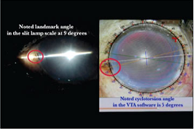
There are a number of systems in the market that are used for toricIOL (intraocular lens) implantation. Many of these require expensive paraphernalia. In this article a new system of axis marking, the Toric Max system (Appasamy Associates) along with a new methodology to identify the numerical value of the exact Cyclotorsion angle involved in the human eye is also considered while the Toric IOL is placed at its designated Placement axis by viewing the 3D monitor during the surgery by the Surgeon and also a 3D overlay Marking Scale for Squint Correction surgery is discussed. It is a cost effective, non- contact digital Toric marking video overlay system with a high level of accuracy. It minimizes too much automation and acquisition of additional equipment. It uses operating surgeon`s skill and facilitates the documentation of captured images of toric IOL placement in the designated axis in real time during the surgical procedure. A 3D overlay marking scale-This conceptualization depicts a 3D Overlay Reference indication on the Human Eye while performing a Squint Surgery – The Overlay design facilitates as an indicator for muscle insertion. These set of measuring scales from 1 to 8mm graduations in steps of 0.5mm and 1 to 10mm graduations in steps of 0.5mm is overlayed over the Human eye image obtained using the 3D camera module attached to an Ophthalmic Operating microscope. It minimizes time taken for each Eye surgery as most of the squint surgeries are done on Pediatric Patients under general anesthesia hence this 3D visual guidance enhances accuracy level of the Squint correction as well as minimizes overall Surgical time involved. No ink marking required, Pooling of blood during the Squint surgery will tend to erase the markings made with the inked instruments so repeated marking is made which might induce an error. The inputs for this software include the entire patient database entry along with the K1 and K2 values of the Patient along with IOL power measurements of the eye undergoing surgery from an A-Scan device, Calculator outputs of any IOL manufacturers’ toric calculator are collected and fed to the built-in offline toric calculator provided in the Toric MAX equipment which are compiled and calculated then later the exact Toric IOL placement details and Cyclotorsion Landmark angles are exported to the VTA software module by the click of a button. A prominent landmark feature is identified from the patient’s eye as a “Landmark Angle”, the location of which is noted from the scale of the slit-lamp by aligning the thin slit beam in-line with a prominent landmark like a mole or a blood vessel in Eye. (Figure 1) This is considered to be the reference to compensate for the cyclotorsion effect. A circular angle-scale as a video overlay appears on the display of this equipment which will guide the surgeon in real-time for indicating the Toric IOL placement axis.
Keywords: Toric marking; Toric overlay; Toric IOLs; Inkless marking; 3D overlay; Squint Correction Surgery; Cyclotorsion compensation; Cyclotorsion angle; Squint markings; 3D video microscope
Introduction
Accurate alignment of astigmatic interventions such as toric intraocular lenses (IOLs) at the intended meridian is essential to achieve the desired astigmatic correction. One degree of off-axis rotation results in a loss of upto 3.3% of intended cylinder correction, if the toric IOL rotates 30 degrees, the magnitude of the refractive cylinder will be unchanged but aligned at a different axis from the preoperative Astigmatism.
Significant errors may be introduced into the process of toric IOL implantation at various steps, for example by tilting of the patient’s head during pre-operative corneal topography, in sitting position (to account for cyclotorsion) manual placement of reference marks on the peripheral cornea (including smearing of ink, thick/broad markings, parallax error, scratching of patient’s cornea etc.), and during intra-operative marking and IOL alignment.
In addition, the surgeon must consider the impact of posterior corneal astigmatism and the healing process. Thus, numerous systems are used during toric IOL implantation to provide for accurate estimation and alignment of the Toric lens. These include systems for measurement of posterior corneal astigmatism, intra-operative wavefront aberrometry, and automated intra-operative registration systems. Intra-operative wavefront aberrometry provides accurate assessment of Toric IOL power and axis. Continuous, real-time refractive feedback for astigmatic correction may be obtained using these systems as seen in Alcon’s Wave Tec Vision Optiwave Refractive Analysis (ORA). Limbal registration may be used to aid accurate alignment as in the Verion Image Guided System (Alcon). They capture a pre-operative image and then recall it during surgery to generate the target meridian on a monitor or through a microscope. All these systems may be provided as an integrated package as with the Zeiss Cataract Suite (Callisto eye). However, these devices lead to a considerable expenditure for the setup. They require an elaborate setup with considerable expenditure, leading to increased cost of the procedure to the patient. There is no accurate method of determining the Numerical value of the exact cyclotorsion angle. Further physically marking the 0 – 180 reference axis with Ink pen or Marker instruments on the patient’s eye can cause injury. Moreover, any improper marking on the eye together with a parallax error caused due to the thickness of the marked line can cause incorrect placement of the ToricIOL.These technologies cumulatively leads to extrapolation of errors which inturn guide the Ophthalmic Surgeon for an inaccurate positioning of the Toric IOLs. A new system called the Toric MAX (Marking Accuracy Expertise) system incorporated with a unique process of Cyclotorsion angle identification. A New procedure of Identification and documentation of the exact Cyclotorsion Angle involved in a Human Eye with a unique Calculation methodology using the Virtual Toric Align Software during Eye Surgeries. Patent Grant No: 402156 with its VTA (Virtual Toric Align) software have been developed recently by an Indian manufacturer (Appasamy Associates) with Truglow 3D Video microscope system. Apart from this New procedure of Identification and documentation of the exact Cyclotorsion Angle involved in a Human Eye with a unique Calculation methodology using the Virtual Toric Align Software during Eye Surgeries and this 3D Overlay system also includes a 3D overlay Marking Scale SquintMAX (Patent Pending No-202341000573) for Squint correction Surgery.
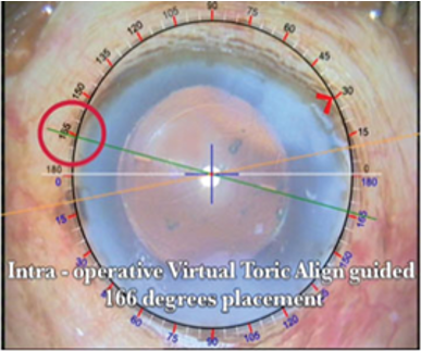
A virtual toric align (VTA) software is designed and used to overlay these axes, using thin, accurate and visible lines of four distinct colours on the surgical video from operating microscope CCD camera.
Figure 2 A Circular scale image along with a Green coloured line for Toric IOL placement axis,White line indicating the 0-180 degree and a Blueline indicating the 0 – 90 degree reference axis Orange coloured line indicating the landmark axis which islocated as per the slit lamp reference angle on the circular angle-scale as a video overlay. This facilitates the operating surgeon with the three axes as indicated above in the figure 2. Once this data is fed in the respective patient database,“Toric Overlay” key is pressed to finalize all the three axes locations which create a ‘Toric Overlay’ to appear on the surgical video from the microscope CCD camera connected to this equipment which appears on a 3D monitor as indicated in Figure 1. A software slider provided with a cursor to be moved left or right to concurrently rotate the Orange coloured landmark axis to coincide exactly on the Surgical table as the same identified land mark in the slitlamp as indicated in figure 1. This invention discloses a safe, easy to implement and accurate method of determination of the exact cyclotorsion angle on the Surgical Table when the Orange coloured Landmark axis is exactly aligned in line with the identified landmark of the Patient in the sitting posture through the slitlamp biomicroscope observation. This same process could be reversed with a unique methodology to reconfirm and verify the applied Cyclotorsion compensation Angle's accuracy level.
Thus, the surgeon apart from positioning the toric IOL to its designated axis by looking directly at the 3D video of the patient’s eye can also use the overlay to accurately locate the incision position, and use visual landmarks to accurately correct for cyclotorsion effect. This is a non contact system which avoids need for pre-operative markings. Measured parameters from A-scan and toric calculators can be transferred directly to the virtual video overlay system. It uses the surgeon’s skill in identifying a scleral, epi-scleral or emissary blood vessel or mole, as a reference mark to accurately measure and record the landmark axis. This eliminates the need for expensive image recognition softwares and complex modifications in the slit lamp and microscope setup. Amongst the various available methods in the market, Toric Max appears to be a promising innovation with a potential to offer accurate axis calculation at a much lower cost.
3D Overlay Marking Scale for Squint Surgeries
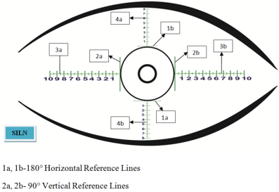
Conventionally all Squint surgeries were performed with calculations and exact measured suturing of the related muscles to achieve an exact correction for that particular Eye. For this reason the Ophthalmic Surgeons will be using marker pens, Calipers to mark the suturing location as per the calculation done. In this 3D Video overlayed Squint MAX system the exact measurement as required by the Ophthalmic Surgeon could be visually guided and indicated by unique scales appearing on the 3D monitor as a Video overlay which visually guides the Surgeon on the exact dimensions required for the related muscles to be sutured. The marking scale is 8mm or 10mm long and is divided into 0.5mm steps. This is a virtual 3D scale which is overlayed on the Surgical field from any reference point by positioning the 90 degree Vertical reference line and 180 degree Horizontal reference line both representing the 0 mm marking of the Scale. This reference point could be fixed on any point on the Eye from where the measurement has to be made in real time during the Surgical procedure moving the X -Y movement of the Ophthalmic microscope Optical head unit to align the Horizontal or Vertical line to coincide the reference point. From this reference point the precaliberated measuring scale will indicate the exact dimension for the Surgeon to locate the desired suturing location of the muscle.
Conventionally all Squint surgeries were performed with calculations and exact measured suturing of the related muscles to achieve an exact correction for that particular Eye. For this reason the Ophthalmic Surgeons will be using marker pens, Calipers to mark the suturing location as per the calculation done. In this 3D Video overlayed Squint MAX system the exact measurement as required by the Ophthalmic Surgeon could be visually guided and indicated by unique scales appearing on the 3D monitor as a Video overlay which visually guides the Surgeon on the exact dimensions required for the related muscles to be sutured. The marking scale is 8mm or 10mm long and is divided into 0.5mm steps. This is a virtual 3D scale which is overlayed on the Surgical field from any reference point by positioning the 90 degree Vertical reference line and 180 degree Horizontal reference line both representing the 0 mm marking of the Scale. This reference point could be fixed on any point on the Eye from where the measurement has to be made in real time during the Surgical procedure moving the X -Y movement of the Ophthalmic microscope Optical head unit to align the Horizontal or Vertical line to coincide the reference point. From this reference point the precaliberated measuring scale will indicate the exact dimension for the Surgeon to locate the desired suturing location of the muscle.
Squint Max overlay scale
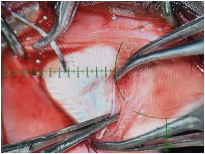
In Figure 4 and Figure 5 illustrates the exact suturing point of the muscle (Superior rectus, Inferior rectus, Lateral rectus, Nasal and oblique muscles) over the sclera could be identified using these guided overlay scales which enable the surgeon to position the muscle to that required measurement as indicated by the divisions on the scales 3a, 3b, 4a, and 4b as 1mm, 1.5, 2, 2.5 ….. 10mm as per the calculation made by the Surgeon for the Squint correction of that particular Eye of the Patient. Fig;6 below indicates the accurate measurement scale for an Oblique muscle suturing measured with a digital vernier when overlayed over a model Eye.
In Figure 4 and Figure 5 illustrates the exact suturing point of the muscle (Superior rectus, Inferior rectus, Lateral rectus, Nasal and oblique muscles) over the sclera could be identified using these guided overlay scales which enable the surgeon to position the muscle to that required measurement as indicated by the divisions on the scales 3a, 3b, 4a, and 4b as 1mm, 1.5, 2, 2.5 ….. 10mm as per the calculation made by the Surgeon for the Squint correction of that particular Eye of the Patient. Fig;6 below indicates the accurate measurement scale for an Oblique muscle suturing measured with a digital vernier when overlayed over a model Eye.
During the entire Squint Surgical procedure, the Surgeon has to gaze at the 3D monitor. For exact placement of the suture needle for the muscle Recession during a Squint surgery, there is an accurate visual guidance by the 3D overlay of the Squint MAX scale indicating as to where the exact point as per the calculation to place the tip of the Suture needle. Figure 7 indicates the conventional blue inked marking coincides exactly the overlay scale and Figure 8 clearly indicates how the Suture needle is placed on the Ocular surface with the guided 3D overlay scale during the Surgical procedure.
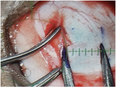
Figure 10: SquintMAX overlay scales guided blue ink marking compared and exact measurements verified with conventional caliper instrument
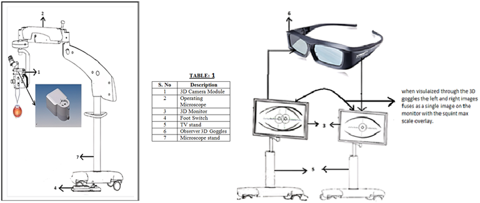
In Figure 11 illustrates the 3D camera module (1) is interconnected with the operating microscope (2). The observer focuses the human eye in the operating microscope (2) using the footswitch (4). The two Left and Right camera outputs from the 3D camera module (1) are connected to the 3D monitor (3) through the video cables. On the 3D monitor (3), the ophthalmic observer can see the 3D overlay squint max scale reference indication as left and right images. When the observer wears observer 3D goggles (6), the two left and right images separately visualized can be combined into a single image. As shown in Figure (8), the observer can see the 3D overlay squint max scale reference indication on the human eye in the 3D monitor (3) with a perfect high depth of focus for squint surgery. It Minimizes time taken for each Eye surgery as most of the squint surgeries are done on Pediatric Patients under general anesthesia hence this 3D visual guidance enhances accuracy level of the Squint correction as well as minimizes overall Surgical time involved. Major advantage is No ink marking required, Pooling of blood during the Squint surgery will tend to erase the markings made with the inked Caliper instrument so repeated marking is made which might induce an error.
Ergonomic Surgeon’s Chair
Specially designed Surgeon’s Chair (Figure 12) with the above Ophthalmic Microscope is for a perfect Gaze angle viewing at the 3D monitor and Ergonomic back rest support for a perfect Sitting posture of the Ophthalmic Surgeon at his own comfort zone during any Ophthalmic Surgical procedure with head and lumbosacral supports. Also enabled with motorized up/down foot control for seat height adjustments and extended Elbow rest to support the Surgeon’s wrist for a controlled manuver of Ocular tissues during the finer movements of the Surgeon hands.
Results
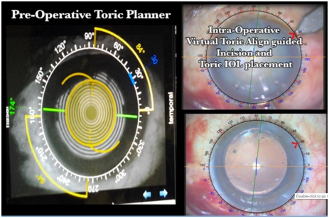
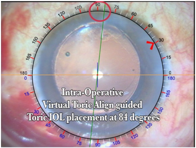
Patient A: Toric IOL placement axis at 84° as indicate by RED circle in Figure 14.
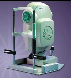
In the above analysed result of a Patient illustrated in Figure 13 and 14 indicate the accurate placement of the Toric IOL at its designated axis Figure 14 as per the GREEN coloured axis indication and the Primary Incision is also made according to the RED > arrow indicator provided by the VTA software of the Toric MAX overlay guidance system. Postoperatively when the Patient Eye is examined immediately 3 hours after the Surgery in the Tracey iTrace (Figure 13 & 15) which is a wavefront aberrometer with a built-in corneal topography, clearly confirms the accurate placement of the Toric IOL exactly at its designated axis location of 84° as calculated by the Pre-Operative Toric Planner software module in the iTrace.
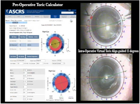
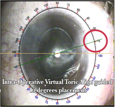
Patient B: Toric IOL placement axis as indicated by the Fig: 16 ASCRS website pre op Toric Calculation is 15°.
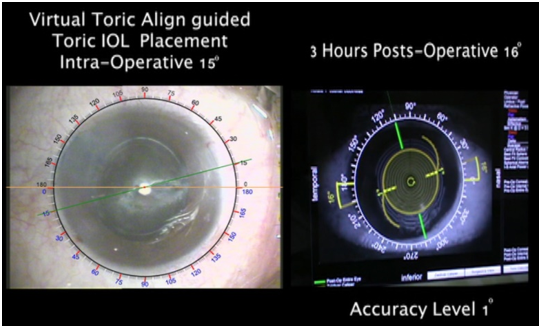
In the above illustrations of Figure 16 and 17 which indicate the Location of the incision made as per the Pre-op Toric Calculator workup and Placement of the Toric IOL at its designated axis as indicated by the Green Axis exactly (Figure 17) at 15°. The RED circular mark depicts the Toric IOL at 15° placement Axis.
In the above Figure 18 and 19, the 3 hours immediate Post operative Patient evaluation on the Tracey i Trace analysis indicated a 16° placement of the Toric IOL instead of its designated angle of 15° which resulted in an accuracy level of only 1° offset for this Patient by the Toric MAX visual guidance system.
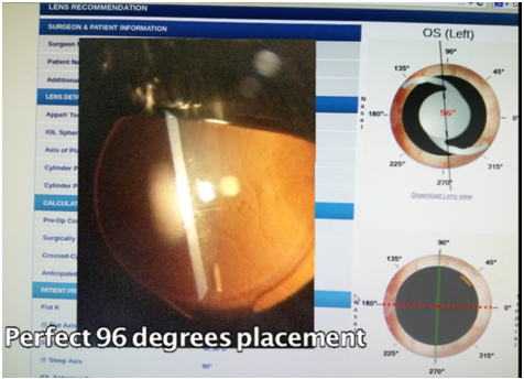
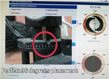
Patient C: For this Patient the Online Toric calculator indicated a placement axis of 96° as indicated in Figure 20.
Accordingly the Toric IOL was dialed and positioned as guided by the Toric MAX overlay guided system and the Post operative follow-up of the Patient under Slitlamp biomicroscope observation revealed the exact 96° Placement angle of the Toric IOL as indicated in Figure 21 and 22.
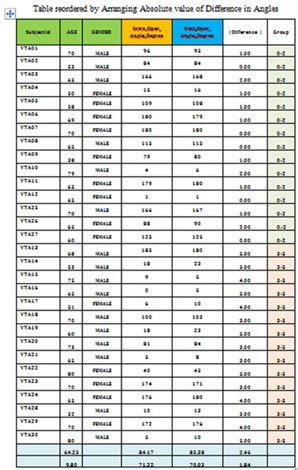
Results after analysing a group of 30 patients the following table in Figure 23 shows that most of the Patients implanted with Toric IOL with Toric MAX overlay guidance system are with an accuracy level of less than 2° difference in angle placements and few of the Patients are with an accuracy level of less than 5° of the Placement angle difference. But these accuracy levels are influenced by many Surgical and Post operative clinical factors which may vary between individual Patients who had undergone Toric IOL implantations.
Conclusion
For perfect Toric IOL placement in your Patient’s Eyes to correct the Corneal Toricity, this Virtual toric align software empowers Ophthalmic Surgeons with complete authenticity. This system also uses Surgeon’s skill with the existing and naturally available technology resource thus minimizing Patient discomfort enhancing Toric IOL placement accuracy levels.
The Squint MAX system also provides dimensions for the accurate placement of the Suture needle for the Muscle recession during a Squint surgical procedure without using any additional inked marking or caliper measurements during the Surgery.
References
- Analysis of ocular cyclotorsion in lying position after peribulbar block and topical anesthesia Newton Kara-Junior HYPERLINK “http://www.scielo.br/scielo.php?
- Universidade de Sao Paulo,Sao Paulo, (SP), Brazil
- Hospital Naval Marcilio Dias, Rio de Janeiro (RJ), Brazil
- Hospital Federal Bonsucsso, Rio de Janeiro(RJ),Brazil
- Surgical management of astigmatism with toric intraocular lenses Bruna V. Ventura HYPERLINK http://www.scielo.br/scielo.php?
- Li Wang HYPERLINK “http://www.scielo.br/scielo.php?
- Department of Ophthalmology, Cullen Eye Institue, Baylor College of Medicine, Houston, Texas, United States of America
- Fundacao Aitino Ventura, Recife, PE, Brazil
- Department of Ophthalmology, Universidade Federal de Sao Paulo,Sao Paulo, SP, Brazil
- VERION Versus Conventional, Manual Ink-markin in Toric IOL Implantation
- This study is currently recruiting participants,
- (HYPERLINK https://clinicaltrils.gov/ct2/show/study/NCT02370953” \I “contacts”)
- Verified November 2015 by Maastricht University Medical Center
Citation: Sivagnanam Subbiah. (2023). A 3D Video Overlay of Angularly and Linearly graduated scales for precisely indicating accurate measures on the Ocular surface in order to Guide Ophthalmic Surgeons during Toric IOL implantation and Squint Surgeries. Journal of Ophthalmology and Vision Research 5(1). DOI: 10.5281/zenodo.7743628
Copyright: © 2023 Sivagnanam Subbiah. This is an open-access article distributed under the terms of the Creative Commons Attribution License, which permits unrestricted use, distribution, and reproduction in any medium, provided the original author and source are credited.

